1. Introduction to switching power supply
Switching power supply products are widely used in industrial automation control, military equipment, scientific research equipment, LED lighting, digital products and instruments and other fields. A switching power supply is a power supply that uses modern power electronics technology to control the turn-on and turn-off time ratio of the switch tube to maintain a stable output voltage. The switching power supply is generally composed of a pulse width modulation (PWM) control IC and a MOSFET.
With the development and innovation of power electronics technology, switching power supply technology is also constantly innovating. At present, switching power supply is widely used in almost all electronic equipment due to its small size, light weight and high efficiency. It is an indispensable power supply method for the rapid development of today’s electronic information industry.
2. Basic components of switching power supply
The switching power supply is roughly composed of four major parts: main circuit, control circuit, detection circuit, and auxiliary power supply.
1. Main circuit
Inrush current limiting: Limit the inrush current on the input side at the moment when the power is turned on.
Input filter: Its function is to filter the clutter existing in the power grid and prevent the clutter generated by the machine from being fed back to the power grid.
Rectification and filtering: directly rectify the grid AC power into smoother DC power.
Inverter: converts rectified DC power into high-frequency alternating current, which is part of the high-frequency switching power supply.
Output rectification and filtering: Provide stable and reliable DC power supply according to load needs.
2. Control circuit
On the one hand, samples are taken from the output terminal, compared with the set value, and then the inverter is controlled to change its pulse width or pulse frequency to stabilize the output. On the other hand, based on the data provided by the test circuit and identified by the protection circuit, it provides The control circuit performs various protection measures on the power supply.
3. Detection circuit
Provide various running parameters and various instrument data in the protection circuit.
4. Auxiliary power supply
Realize the software (remote) startup of the power supply to provide power for the protection circuit and control circuit (PWM and other chips).
3. Working principle of switching power supply
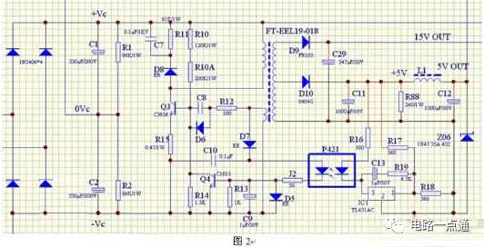
The voltage conversion of the switching power supply is a pulse oscillator composed of switching transistors, pulse transformers, etc., which generates pulse electricity and converts 300V DC into the required voltage through the secondary of the pulse transformer. The electrical principle is shown in Figure 2.
1. Working principle of pulse oscillator
1) Starting of pulse oscillator
The power supply provides forward bias voltage to the b pole (base) and e pole (emitter) of Q3 (transistor) through R10, R10A, and R15, forcing Q3 to enter the conductive state.
2) Oscillation process of pulse oscillator
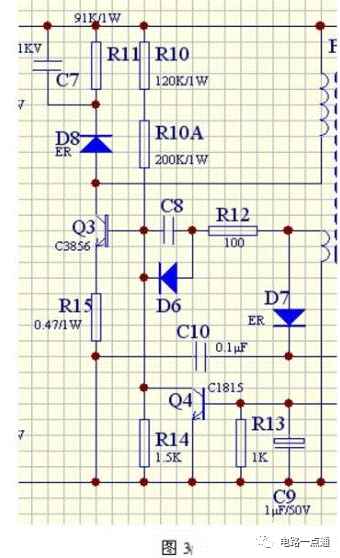
When Q3 enters the conduction state, +Vc will pass through the primary coil of the pulse transformer, the c pole, e pole of Q3, and R15 to the -Vc of the power supply. At this time, the secondary coil of the pulse transformer will generate an induced potential, and the secondary One end of the coil is connected to -Vc, and the other end is connected to the b pole of Q3 via R12 and C8, and the polarity of the induced potential is the same as the self-induced potential of the primary coil (the upper ends of the primary coils in the figure have the same name) terminal), the b-pole of Q3 will get a larger base current, accelerating the conduction of Q3 until Q3 enters a saturated state. The circuit is shown in Figure 3.
When Q3 is saturated, Ic no longer changes, and the waveform is from t0 to t3 in Figure 4. After the saturation process from t3 to t4, the polarity of the self-induced electric potential and the induced electric potential will be reversed, that is, negative up and positive down. The reversed potential in the secondary coil is added to the e-pole of Q1 via R15, and the negative pole is added to the b-pole of Q3 via R12 and C8, causing Q3 to be reverse biased and prompting Q3 to quickly transition from the saturated state to the Cut-off state, t4 to t6 in the figure. After Q3 is cut off, the reverse potential and reverse current generated in the primary coil are quickly absorbed through the absorption circuit composed of D8, R17, and C7, from t6 to t7 in the figure. An oscillation cycle is completed. Then the oscillator circuit will repeat the above process over and over again.
The frequency of the pulse oscillator is determined by C8 and the inductance of the connected secondary coil.