What is the power supply?
A power supply is an electrical device that converts current from an energy source (such as a power grid) into the voltage required by a load (such as a motor or electronic device).
There are two main designs of power supplies: linear power supplies and switching power supplies.
Linear Power Supply: Linear power supply designs use a transformer to step down the input voltage, then rectify and convert the voltage to a DC voltage, which is then filtered to improve waveform quality. Linear power supplies use linear regulators to keep the output voltage constant. Linear regulators dissipate any excess energy in the form of heat.
Switching Power Supply: Switching power supply design is a newer approach that solves many of the problems present in linear power supply design, including transformer size and voltage regulation issues. In a switching power supply design, the input voltage is no longer reduced, but is rectified and filtered at the input; it is then converted into a high-frequency pulse sequence by a chopper; it is filtered and rectified again before the voltage reaches the output.
Table of Contents
Working principle of switching power supply
Linear AC/DC power supplies have long been used to convert alternating current from the utility grid to direct current for use in home appliances or lighting. But high-power applications increasingly require smaller power supplies. Linear power supplies have been relegated to specific industrial and medical uses, where their low noise still makes them useful; switching power supplies have largely replaced them because of their small size, high efficiency and ability to handle high power. linear power supply. Figure 1 illustrates the general conversion process from alternating current (AC) to direct current (DC) in a switching power supply.

Figure 1: Isolated AC/DC switching power supply
Input rectification
Rectification is the process of converting AC voltage into DC voltage. Rectification of the input signal is the first step in switching mode AC/DC power supplies.
DC voltage is usually thought of as a constant straight-line voltage, like that provided by a battery. But in reality, direct current (DC) is defined as a unidirectional flow of charge. This means that the DC voltage flows in the same direction, but is not necessarily constant.
Sine Wave Alternating Current (AC) The sine wave is the most typical voltage waveform, with the first half of the cycle being positive and the second half of the cycle being negative. If the negative half-cycle is inverted or eliminated, the current will stop alternating and become DC. This conversion process can be achieved through rectification.
Rectification is achieved by using diodes in a passive half-bridge rectifier to eliminate the negative half of the sine wave (see Figure 2). The diode allows current to pass during the positive half-cycle of the wave and blocks the current when it flows in the opposite direction.
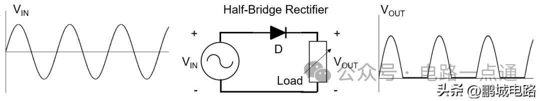
Figure 2: Half-bridge rectifier
A rectified sine wave will have a low average power and will not be able to effectively power a device. Another, more effective method is to change the polarity of the negative half-wave, turning it into a positive wave. This method is called full-wave rectification, and it only requires four diodes in a full-bridge configuration (see Figure 3). This configuration ensures stable current direction regardless of the polarity of the input voltage.
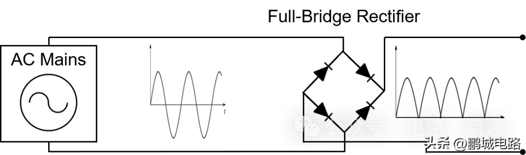
Figure 3: Full-bridge rectifier
Compared to half-bridge rectification, the average output voltage of the full-wave rectified waveform is higher, but it is still far from the constant DC waveform required to power electronic equipment. Although it is already a DC waveform, it can be seen from the shape of the voltage wave that the voltage changes very quickly and frequently, and using such DC to power equipment will be inefficient. This periodic variation in DC voltage is called ripple, and reducing or eliminating ripple is critical to achieving an efficient power supply.
The simplest and most common way to reduce ripple is to add a large capacitor, called a storage capacitor or smoothing filter, to the rectifier output (see Figure 4).
This capacitor stores voltage during the peak of the wave and then supplies current to the load until its voltage is less than the rising rectified voltage wave. The waveform it produces will be closer to the desired shape and can also be thought of as a DC voltage without an AC component. This final voltage waveform can power DC equipment.
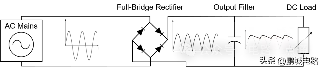
Figure 4: Full-bridge rectifier with smoothing filter
Passive rectifiers use semiconductor diodes as uncontrolled switches, which are the simplest method of rectifying AC waves, but are not the most efficient.
Diodes are relatively efficient switches. They turn on and off quickly with minimal power consumption. But the only problem with it is that there is a forward bias voltage drop of 0.5V to 1V, which reduces efficiency.
Active rectifiers replace diodes with controllable switches, such as MOSFETs or BJT transistors (see Figure 5). It has two advantages: first, transistor rectifiers do not have the 0.5V to 1V voltage drop inherent in semiconductor diodes because their resistance can be arbitrarily small and therefore the voltage drop is also small; second, the transistor is a controlled switch, which means that the switching frequency can be Adjust and optimize.
The disadvantage is that active rectifiers require more complex control circuits to achieve their goals, which require additional components and therefore cost more.
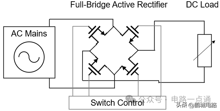
Figure 5: Full-bridge active rectifier
Power factor correction (PFC)
The second step in switching power supply design is power factor correction (PFC).
PFC circuits contribute little to the actual conversion of AC to DC, but they are an important part of most commercial power supplies.
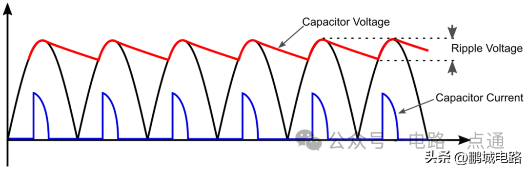
Figure 6: Voltage and current waveforms at the rectifier output
Looking at the current waveform of the rectifier storage capacitor (see Figure 6), you will see that the charging current flows through the capacitor in a very short time span; specifically, from the point at which the voltage at the input of the capacitor is greater than the capacitor charge, to the point where the rectified signal between peaks. This causes a series of short current spikes in the capacitor, causing serious problems not only for the power supply but also for the entire grid. Because these current spikes are injected into the grid and generate a large number of harmonics. Harmonics create distortion that can affect other power sources and equipment connected to the grid.
In the design of switching power supply, the purpose of the power factor correction circuit is to filter out these harmonics and minimize them. There are two types of power factor correction circuits: active and passive.
Passive PFC circuits consist of passive low-pass filters that attempt to eliminate high-frequency harmonics. However, passive PFC alone does not allow power supplies, especially in high-power applications, to comply with international harmonic noise specifications. Active power factor correction must be used.
Active PFC can change the shape of the current waveform so that it follows the voltage waveform. The harmonics are shifted to higher frequencies and are therefore easier to filter out. In this case, the most commonly used circuit is a boost (or step-up) converter.
Isolation: Isolated and non-isolated switching power supplies
Regardless of the presence of a PFC circuit, the final step in power conversion is to reduce the rectified DC voltage to an appropriate magnitude for the intended application.
Since the incoming AC waveform is rectified at the input, the DC voltage output is very high: without PFC, the output DC voltage of the rectifier will be approximately 320V; with the active PFC circuit present, the output of the boost converter will be 400V or more High stable DC voltage.
High voltages in both cases are extremely dangerous and unnecessary for most applications that require very low voltages. Table 1 lists several aspects that should be considered when selecting the correct isolation topology, including converter and application.
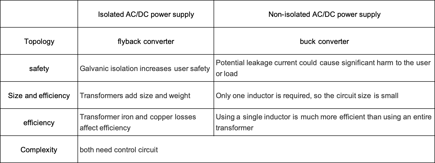
Table 1: Isolated and non-isolated AC/DC power supplies
The choice of blood pressure reduction method is mainly related to safety.
The input side of the power supply is connected to the AC mains, which means if there is a leakage at the output, a shock of this magnitude can cause serious injury or even death, and can damage any equipment connected to the output.
Safety is ensured by magnetically isolating AC/DC power input and output circuits connected to the power mains. The most widely used circuits in isolated AC/DC power supplies are flyback converters and resonant LLC converters because they both have electrical or magnetic isolation (see Figure 7).
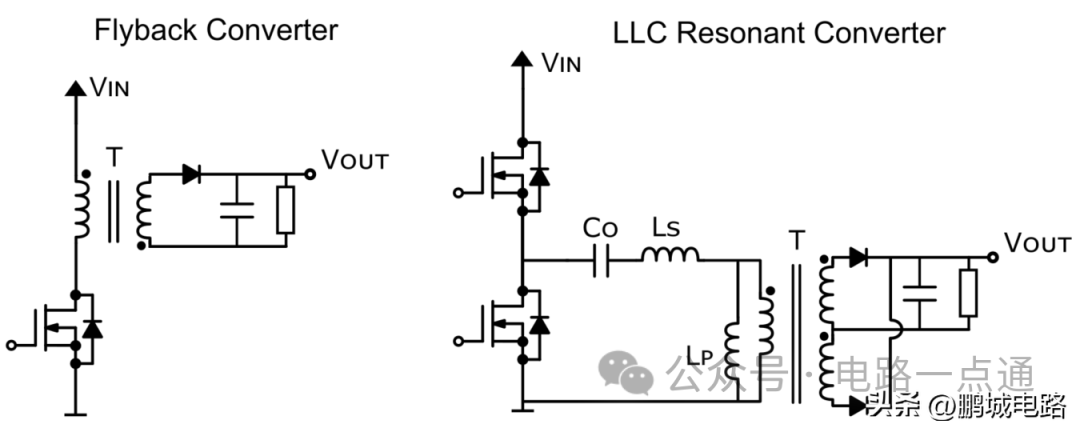
Figure 7: Flyback converter (left) and LLC resonant converter (right)
Using a transformer means that the signal cannot be a flat DC voltage. Instead, the voltage must change, and therefore the current must change, so that energy can be transferred from one side of the transformer to the other via inductive coupling. Therefore, both flyback and LLC converters “chop” the input DC voltage into a square wave, which is then stepped down through a transformer. Finally, the waveform is rectified again before output.
Primarily used in low power applications, a flyback converter is also an isolated buck-boost converter whose output voltage can be higher or lower than the input voltage, depending on the relationship between the primary and secondary windings of the transformer. turns ratio.
The operation of a flyback converter is very similar to that of a boost converter.
When the switch is closed, the primary coil is charged by the input and forms a magnetic field; when the switch is opened, the charge in the primary inductor is transferred to the secondary winding, which injects current into the circuit, thereby powering the load.
The flyback converter is relatively easy to design and requires fewer components than other converters, but it is not efficient because it forces the transistor to turn on and off at will, and this hard switching causes huge losses (see Figure 8). Especially in high-power applications, this shortens transistor life and creates huge power dissipation. Therefore, the flyback converter is more suitable for low power applications where the power is usually up to 100W.
Resonant LLC converters are commonly used in high power applications. Its circuit is also magnetically isolated via a transformer. LLC converters are based on the phenomenon of resonance, which means that when the operating frequency matches the natural frequency of the filter, this frequency will be amplified. In this case, the resonant frequency of the LLC converter is defined by the series inductor and capacitor (LC filter) and is also affected by the additional effect of the primary inductance (L) of the transformer, hence the name LLC converter.
LLC resonant converters are preferred for high-power applications because they can produce zero-current switching, also known as soft switching (see Figure 8). When the current in the circuit is close to zero, it can turn the switch on and off, minimizing the switching losses of the transistor, thereby reducing EMI and improving efficiency. However, this performance improvement comes at a price: It is very difficult to design an LLC resonant converter that can achieve soft switching under various load conditions. To this end, MPS has developed a special LLC design tool that ensures that the converter operates at the correct resonance state, thereby achieving better switching efficiency.
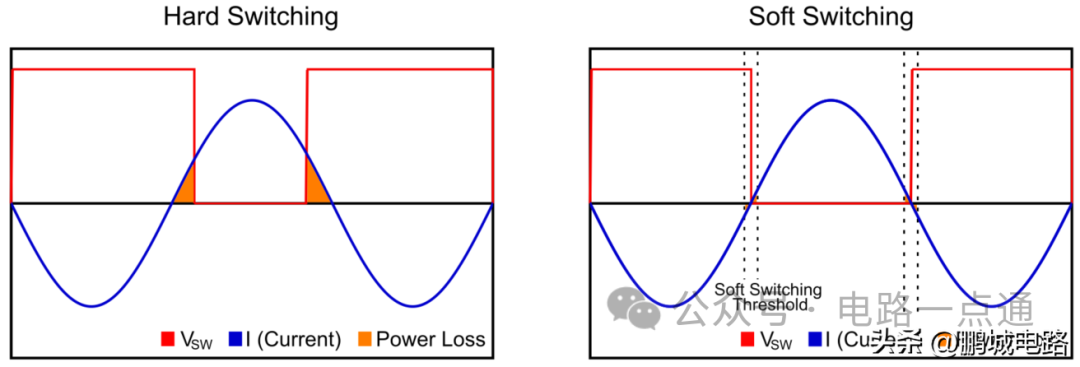
Figure 8: Hard switching (left) and soft switching (right) losses
As mentioned earlier, one of the limitations of AC/DC power supplies is the size and weight of the input transformer. This is because the low operating frequency of the input transformer (50Hz) requires a larger inductor and core to avoid saturation.
In switching power supplies, the oscillation frequency of the voltage is significantly higher (at least above 20kHz). This means that the step-down transformer can be smaller because high-frequency signals create less magnetic losses in the linear transformer. As the size of the input transformer becomes smaller, the system can be miniaturized, making it possible to fit the entire power supply into a mobile phone charger, like what we use now.
Some DC equipment does not require a transformer to provide isolation. This is common in devices that do not require direct user touch (e.g. lights, sensors, IoT, etc.) since any processing of device parameters is done on a separate device (e.g. phone, tablet or computer).
This has significant benefits for the weight, size and performance of the device. These converters reduce the output voltage level using a high voltage buck converter. Its circuit can be considered as the inverting circuit of the boost converter mentioned before. In this case, when the transistor switch is closed, the current flowing through the inductor creates a voltage across the inductor, which cancels the voltage from the supply, thereby reducing the voltage at the output. When the switch is opened, the inductor delivers current to the load, maintaining the voltage across the load when the circuit is disconnected from the power source.
AC/DC switching power supplies use high-voltage buck converters because the MOSFET transistors acting as switches must be able to withstand large voltage changes (see Figure 9). When the switch is closed, the voltage across the MOSFET is close to 0V; but when it is open, this voltage rises to 400V in a single-phase application and to 800V in a three-phase converter. These sudden high voltage changes can easily damage ordinary transistors, so special high voltage MOSFETs are used.

Figure 9: Non-isolated AC/DC switching power supply with active PFC
A buck converter is easier to integrate than a transformer because it requires only one inductor. Its voltage-reducing efficiency is also higher, with efficiency up to 95% under normal conditions. This high efficiency is achieved because the transistors and diodes consume almost no switching power, with the only losses coming from the inductor.
Summarize
AC/DC switching power supplies are currently the most efficient method of converting AC power to DC power. Its power conversion is divided into three stages:
1. Input rectification: The input mains AC voltage is converted into a DC rectified wave through a diode bridge. Adding a capacitor to the output of the bridge can reduce the ripple voltage.
2. Power factor correction (PFC): Due to the presence of nonlinear current in the rectifier, the harmonic content of the current is very large. There are two ways to solve this problem: one is to use passive PFC, which uses filters to suppress harmonic effects, but this method is not efficient; the second method is called active PFC, which uses switches to voltage converter so that the current waveform follows the input voltage waveform. Active PFC is the only way to enable power converters to meet current size and efficiency standards.
3. Isolation: Switching power supply can be isolated or non-isolated. A device is isolated when the input and output of a power supply are not physically connected. Isolation can be achieved through a transformer, which electrically isolates the two halves of the circuit. But transformers can only transmit power when the current changes, so the rectified DC voltage is chopped into a high-frequency square wave and then transmitted to the secondary circuit; it is then rectified again and finally passed to the output.
Designing a switching power supply requires consideration of all aspects, especially safety, performance, size and weight. The control circuitry of switching power supplies is also more complex than that of linear power supplies, and many designers find it helpful to use integrated modules in the power supply.